
NEC 2026: Energy Management Moves to Article 130, and a PCS Setting Goes in the Load Calc
A 200 A service that’s already close to full used to mean one thing when the customer wanted an EV charger: a service upgrade. The 2026 NEC gives you a cleaner way to put a listed controller in the load calculation instead.
Energy management systems moved from Article 750 to a new Article 130 in Chapter 1, right behind the load calculations in Article 120. The rule that lets you use a controller’s setting in the calc moved too, from 220.70 to 120.7, and it now speaks about power control systems (PCS).
The short version
- Article 750 is now Article 130. Part I covers every energy management system (EMS); new Part II covers power control systems.
- A PCS is an EMS that prevents overloads. Only a PCS can change your load calculation, and it has to be listed as one.
- 220.70 is now
120.7. It applies to branch circuits, feeders and services. - The setting tops out at 80% of the rating of the overcurrent device on the circuit the PCS monitors.
- What goes in the calc depends on what the PCS monitors: the control setting, or the controlled load’s minimum operating current.
What moved, and where it went
Article 750 arrived in the 2014 NEC. In 2026 its content sits in Article 130 so that it’s next to the calculations it affects. The EV and solar sections that point to it were retitled to match.
| Topic | 2023 NEC | 2026 NEC |
|---|---|---|
| Energy management systems (whole article) | Art. 750 | Art. 130 |
| Power control systems | — | Art. 130, Part II (new) |
| Using a controller setting in a load calc | 220.70 | 120.7 |
| Noncoincident loads | 220.60 | 120.6 |
| EV charging load under a controller | 625.42(A) | 625.42(A), now titled for PCS |
| Solar and storage current limiting | 705.13 | 705.13, now titled for PCS |
EMS or PCS: the difference that matters on a permit
Under the revised definition, an energy management system monitors loads and controls loads. Think of a building controller that sheds lighting to trim a demand charge. That’s useful, but it isn’t built to protect conductors.
A power control system is an EMS that also prevents overloads. It watches the current on a circuit, feeder or service and turns the loads it manages down or off before the limit is passed. The 2026 Code adds a definition with two types: single-source, for an ordinary utility service, and multisource, for sites with solar, batteries or a microgrid.
The listing rule in 130.2 follows that split. Energy management equipment has to be listed, and equipment that does overload control has to be listed as a PCS. UL evaluates power control systems under UL 3141. If the cut sheet only says “energy management” or “load management,” ask the manufacturer for the PCS listing before you put the setting in a calculation.
Two loads that listed equipment keeps from running at the same time, such as an interlocked pair, fall under the noncoincident-load rule in 120.6. A system that modulates loads to stay under a limit falls under 120.7.
How 120.7 works
120.7 has three conditions.
- The PCS complies with Article 130, Part II. That brings in the listing, malfunction, settings and marking rules.
- A qualified person picks the control setting, and it can’t be more than 80% of the rating of the overcurrent device for the monitored circuit. On a 200 A service that’s 160 A. On a 100 A service, 80 A. This limit is new in 2026.
- You split the loads into controlled and noncontrolled. Noncontrolled loads are calculated the normal Article 120 way. The controlled loads depend on where the PCS is measuring.
| The PCS monitors | Value used for the controlled loads | Typical setup |
|---|---|---|
| Only the controlled loads | The PCS control setting | Power-sharing EV chargers on their own feeder |
| Controlled and noncontrolled loads together | The controlled loads’ minimum operating current (can be 0 A) | Sensors on the service conductors, charger throttled by the PCS |
The second row is the one that saves service upgrades. If the PCS sees the whole service and can take the charger down to zero, the charger adds nothing to the calculated load.
Worked example 1: PCS on the service
This follows the dwelling example in Informative Annex D of the 2026 NEC, as described in Electrical Contractor magazine. A new home calculates to 29,040 VA, which is 121 A at 240 V. The utility can only supply a 100 A service. One of the loads is a 50 A EV charger (12,000 VA) that a PCS can throttle from 50 A down to 0 A. The PCS monitors the service, and a qualified person sets it at 80 A, which is 80% of the 100 A service overcurrent device.
| Step | Without PCS | With PCS (120.7) |
|---|---|---|
| Noncontrolled loads (Article 120) | 17,040 VA | 17,040 VA |
| EV charger, 50 A at 240 V | 12,000 VA | 0 VA (minimum operating current) |
| Total | 29,040 VA | 17,040 VA |
| At 240 V | 121 A | 71 A |
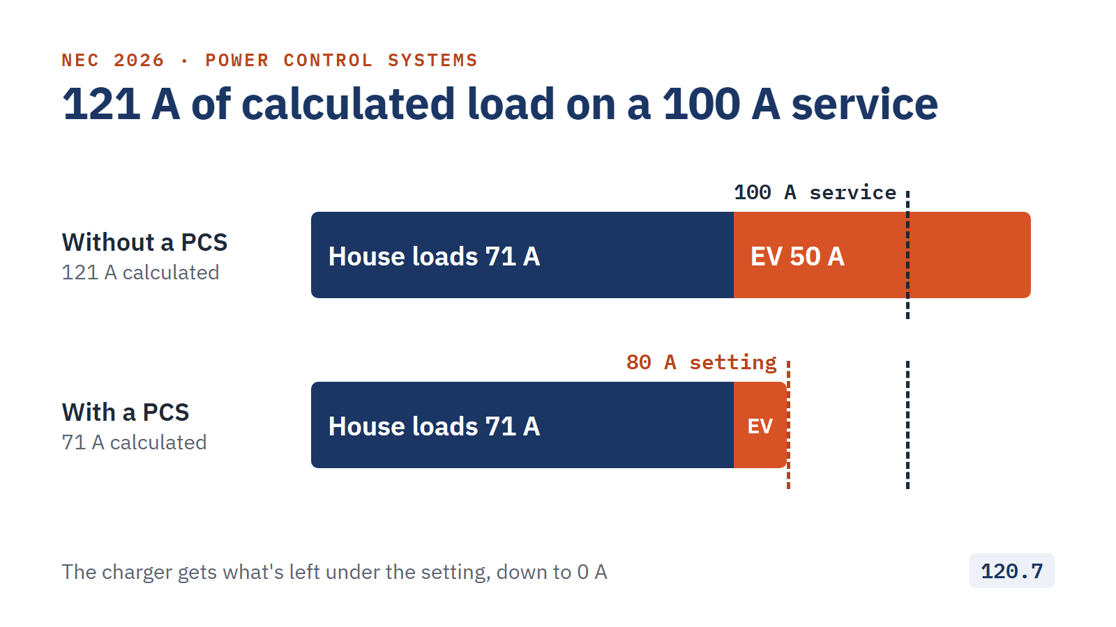
The calculated load drops by 50 A and fits the 100 A service. In operation the charger runs on whatever is left under the 80 A setting and waits when the house is busy.
Worked example 2: PCS on the EV feeder only
An existing home has a 200 A service and calculates to 118 A. The owner wants two 48 A chargers. EV charging is a continuous load, and the two chargers add 96 A.
| Step | No PCS | PCS on EV feeder |
|---|---|---|
| Existing house load | 118 A | 118 A |
| Two 48 A chargers | 96 A | 48 A (control setting) |
| Total on the 200 A service | 214 A | 166 A |
Here a listed power-sharing system monitors only the EV feeder, which has a 60 A breaker. The highest setting allowed is 80% of 60 A, or 48 A, and because the PCS doesn’t see the house loads, that setting is the number that goes in the calc. Article 130 treats the setting as a continuous load, so the feeder math still closes: 48 A × 125% = 60 A. Even with the 125% carried to the service, 118 + 60 = 178 A.
The 118 A figure is an assumed starting point for illustration. Under 625.42(A), the EV load on a service or feeder is the maximum the PCS permits, and chargers with built-in load management have to be marked to show it.
What about heat pumps and water heaters?
120.7 isn’t limited to EV chargers. It talks about controlled loads in general. The practical limits are the listing and the customer. The PCS has to be listed to control that equipment, and whatever it controls can be turned down when the house is busy. A charger that waits an hour is no problem. Space heating in January is a different conversation, so most designs leave heating and cooling as noncontrolled loads and manage the charger or the water heater.
Some loads are off the table. Article 130 doesn’t let an EMS disconnect things like elevators, emergency lighting circuits, or ventilation for hazardous locations.
What the inspector will look for
Part II of Article 130 runs from 130.50 to 130.80. The parts that show up at inspection:
- Fail-safe behavior. If the PCS loses a sensor or communication, it has to go to a controlled state that still prevents overload.
- Locked settings. Settings are in amperes, and only qualified persons can change them, using the access method in the listing.
- Marking. The equipment is marked with the control setting, what the PCS manages, and a notice that the circuits are under PCS control. Outside dwellings, add the calculation date and who set it.
- Documentation and directory. Keep a record of the functions, equipment and settings, state whether the PCS is single-source or multisource, and post a directory when the controller isn’t within sight of the breakers it controls.
Checklist for a PCS load calc
- Confirm the adopted edition: 120.7 and Article 130 (2026) or 220.70 and Article 750 (2023)
- Get proof the equipment is listed as a PCS, not just as an EMS
- Note where the PCS measures: controlled loads only, or the whole feeder or service
- Keep the setting at or under 80% of the monitored overcurrent device
- Use the control setting or the minimum operating current, whichever the monitoring point calls for
- Show the setting, the controlled loads and the PCS type on the plans and on the equipment label
Run the numbers
Enter the service, the controlled loads and the PCS setting, and get a permit-ready PDF in minutes.
Educational content only. This article paraphrases and does not reproduce NFPA 70 text. Code adoption and amendments vary by jurisdiction. Verify with your AHJ and a licensed professional.
FAQ
Where is Article 750 in the 2026 NEC?
It moved to Article 130 in Chapter 1. Part I covers energy management systems in general and Part II covers power control systems.
What is the difference between an EMS and a PCS?
An EMS monitors and controls loads. A PCS is an EMS that also prevents overloads on conductors and equipment, and it has to be listed as a PCS. Only a PCS can be used in a load calculation under 120.7.
How high can a PCS control setting be?
No more than 80% of the rating of the overcurrent device for the circuit the PCS monitors: 160 A on a 200 A service, 80 A on a 100 A service.
Can a PCS help me avoid a service upgrade for an EV charger?
Often, yes. If the PCS monitors the service and can throttle the charger to 0 A, the charger is counted at its minimum operating current in the calculation. Your AHJ’s adopted edition and the equipment listing decide whether it’s accepted.
- EC&M: Top 25 changes to the 2026 National Electrical Code
- EC&M: Key revisions to Chapter 1 of the 2026 NEC
- Electrical Contractor: The 411 on EMS and PCS
- Electrical Contractor: Load control, calculations for monitored and nonmonitored loads
- UL Solutions: Article 130, energy management systems
- EC&M: Safe load management for electrified homes